

Contents
- SLAM Technology and Equipment
- Practical Applications of SLAM in Surveying
- Point Cloud Colourisation and Panoramas
- Data Processing in SLAM GO POST
- Office Processing and Vectorisation
- Accuracy, Data Density, and Error Accumulation
- Performance and Hardware Requirements
- Practical Recommendations and Conclusions
The TOPODRONE team held a webinar demonstrating the use of SLAM-based mobile laser scanners for the production of large-scale topographic plans at a scale of 1:200. The session covered the complete workflow — from field data acquisition through to the delivery of the final topographic drawing. The key findings and recommendations from the webinar are summarised below.
A recording of the webinar is available at the following link:
SLAM Technology and Equipment
SLAM systems integrate data from a LiDAR sensor, an inertial measurement unit (IMU), and cameras to generate a point cloud in real time as the operator moves through the site. As a baseline example, the SLAM 100 model is used, featuring three integrated 5 MP cameras. To improve the quality of point cloud colourisation, external panoramic cameras — such as the Insta360 X4 — can be connected, providing higher-resolution and more detailed imagery.
The SLAM 200 and SLAM 200E represent further developments of the SLAM 100 platform. These scanners are equipped with two 12 MP cameras and Hesai XT16 or XT32 LiDAR units, offering a scanning range of up to 300 m.
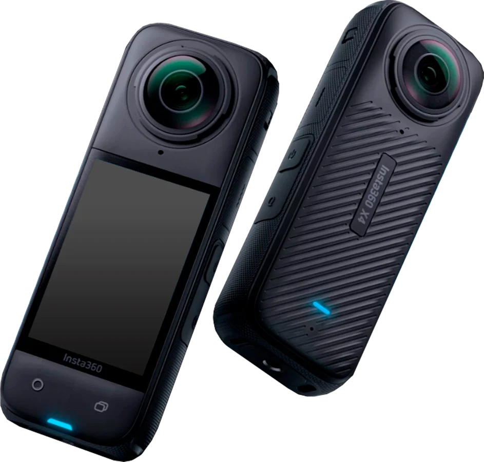
Image 1. Camera Insta X4
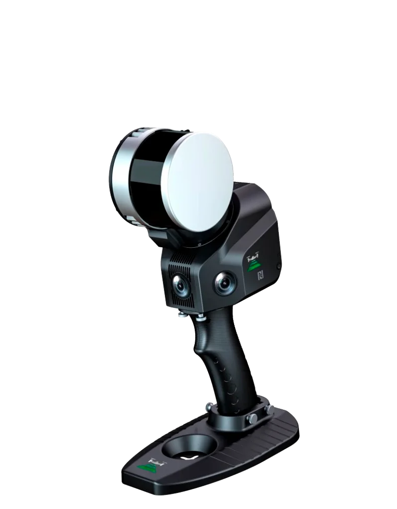
image 2. SLAM 100
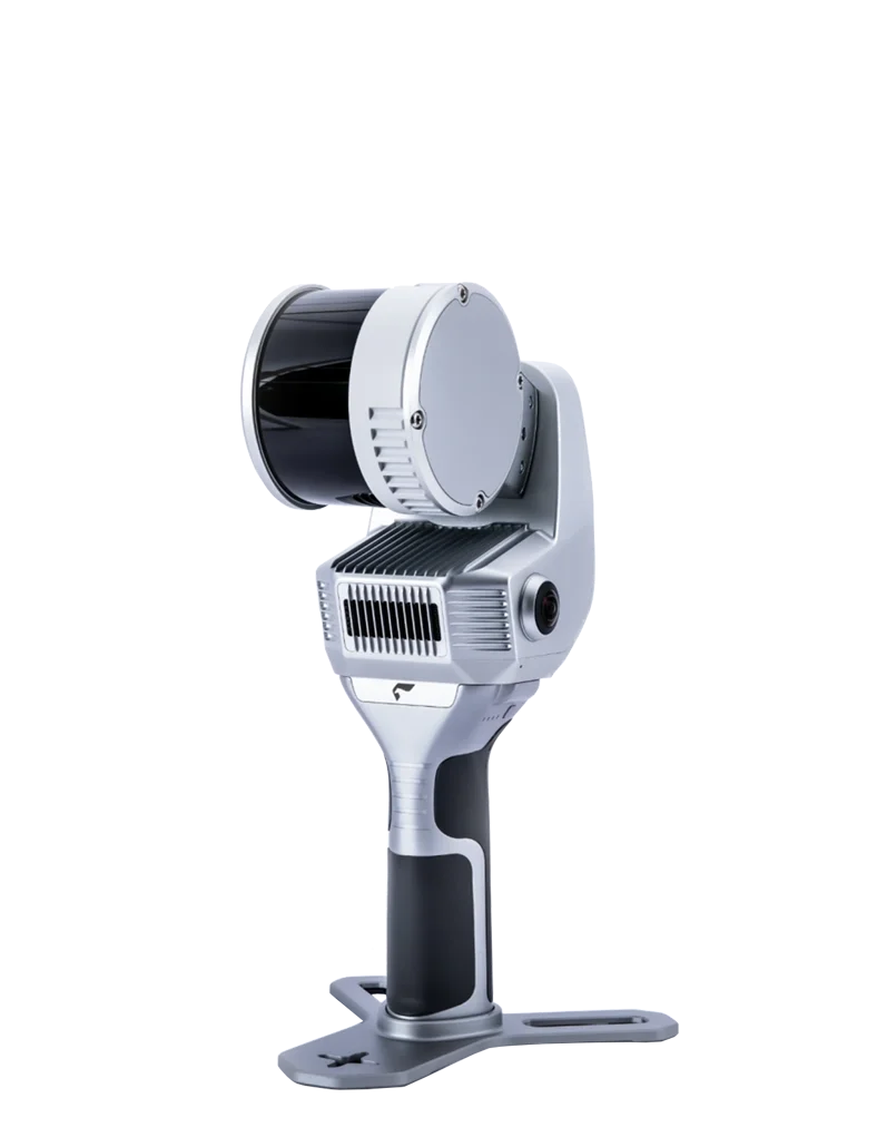
Image 3. SLAM 200
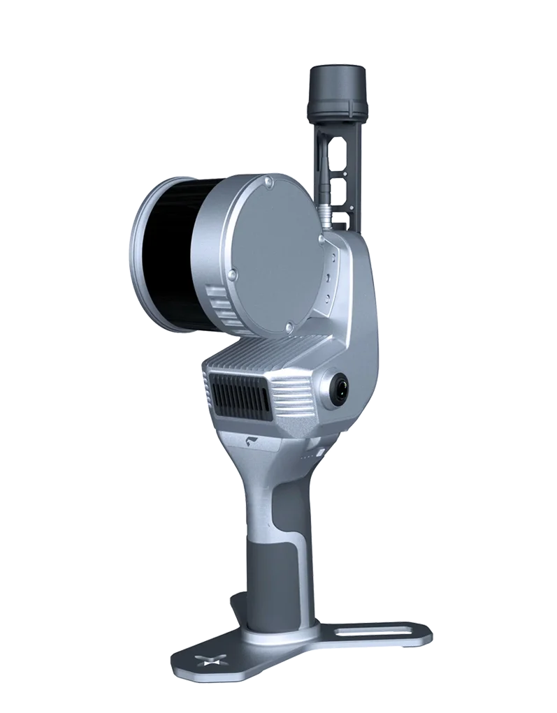
Image 4. SLAM 200E
Comparative Table of the Key Specifications of SLAM 100, SLAM 200E, and SLAM 200
| Technical parameters | SLAM 200E | SLAM 200 | SLAM 100 |
|---|---|---|---|
| Dimensions | 404 × 170 × 188 mm | 185 × 170 × 404 mm | 372 × 163 × 106 mm |
| Weight | 1.6 kg (2.1 kg with battery) | 1.3 kg (1.8 kg with handle) | 1.59 kg |
| Operating range | 120 m | 300 m | 120 m |
| Scanning rate | 320 / 640 thousand pts/s | 640 thousand pts/s | 320 thousand pts/s |
| Field of view | 360° × 270° | 360° × 270° | 360° × 270° |
| Camera resolution | 12 MP | 12 MP | 5 MP |
| Data accuracy | ≈ 2 cm | ≈ 2 cm | 3–5 cm |
| GNSS / RTK | Integrated | Integrated | External module |
| GNSS-denied operation (SLAM) | Yes | Yes | Yes |
| Batteries | Internal | Internal | 4 × replaceable 3350 mAh |
| Operating temperature | –20 to +50 °C | –20 to +50 °C | –10 to +45 °C |
Practical Applications of SLAM in Surveying
The practical value of SLAM technology becomes particularly evident in environments where conventional GNSS receivers and total stations perform unreliably — for example, in areas affected by satellite signal interference or in sites with complex terrain and obstructed visibility. In such conditions, mobile SLAM scanners enable rapid data acquisition for topographic surveying, cadastral and mine surveying tasks, as well as landscape design applications, operating independently of satellite-based navigation systems.
As a practical example, a site survey covering an area of approximately 0.4 hectares with a high density of small features was presented. Data capture was carried out manually, using a dense network of walking trajectories with mandatory loop closures, which helped to minimise the accumulation of drift and systematic error.
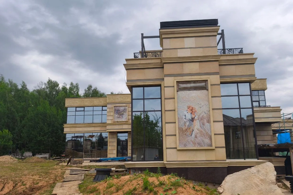
Image 5. Building on the surveyed site
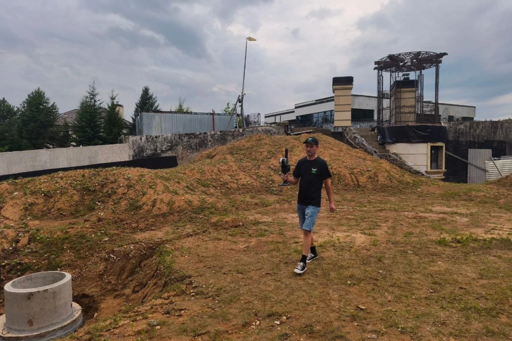
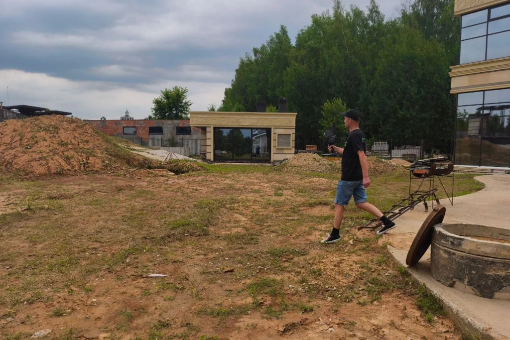
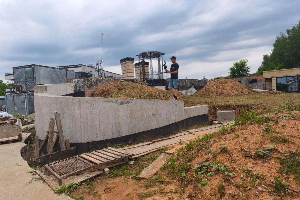
Image 6-8. Site scanning using the SLAM 100
For open areas, traversal spacing of 15–25 m is generally sufficient. On more complex sites, the spacing is reduced and supplemented with additional passes inside buildings or at underground levels. Accurate georeferencing is achieved using ground control points (GCPs) — a minimum of three per site, with optimal placement at intervals of 150–250 m around the perimeter and within the central area. Where a stable RTK signal is available, direct georeferencing of the point cloud is possible; however, in practice, a GCP-based control scheme is more commonly applied.
Point Cloud Colourisation and Panoramas
Following the completion of fieldwork, point cloud colourisation (RGB attribution) represents a critical processing stage. In the SLAM 100 system, colour capture is performed by three integrated cameras; however, when external panoramic cameras such as the Insta360 X4 are connected, the resulting colour information becomes significantly more detailed.
Georeferenced panoramic images are stored together with the camera’s positional and orientation data and are subsequently used during office processing to refine small features, support object interpretation, and assist with manual vectorisation.
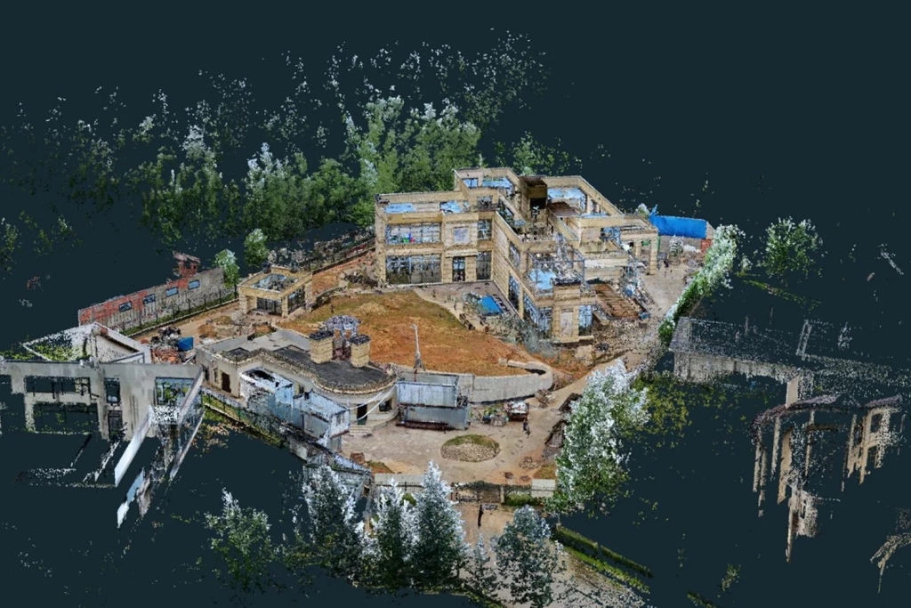
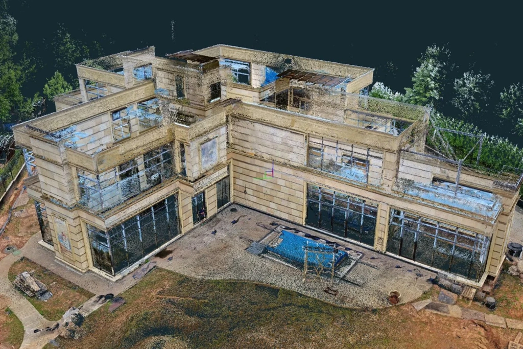
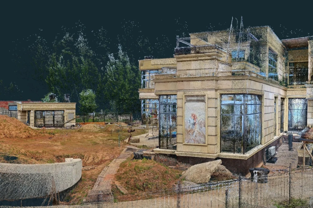
Image 9-11. RGB point cloud
Data Processing in SLAM GO POST
For post-processing, the proprietary SLAM GO POST software supplied with the hardware is used. The workflow is highly automated: the user imports the LiDAR and IMU data, specifies the scanner mounting configuration (handheld, backpack-mounted, or vehicle-mounted), and selects the appropriate processing algorithm.
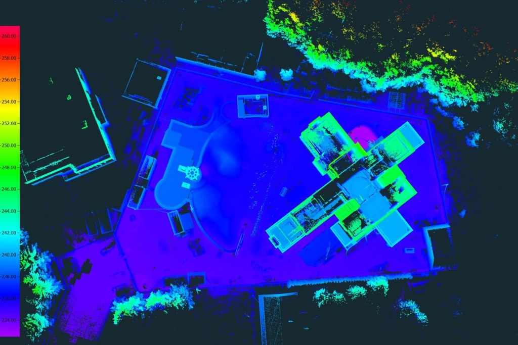
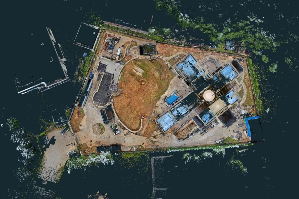
Image 12–13. Point cloud by elevation and in RGB
Two processing modes are available:
Algorithm A (Fast) — a high-speed mode with minimal scan matching. It is typically used when processing time is the primary concern, for example when surveying large forested areas.
Algorithm B (High Precision) — a slower but more detailed mode that provides robust trajectory linking between passes and accurate point cloud registration.
Practical experience shows that selecting the appropriate algorithm is critical: in some cases, switching from the High Precision mode to the Fast mode can eliminate duplicated linear features and improve overall result stability.
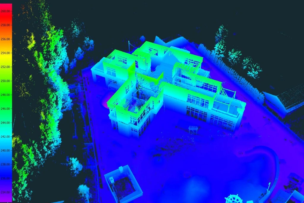
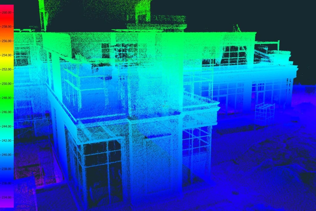
Image 14–15. Elevation-based point cloud
Upon completion of processing, a unified point cloud is generated in the specified coordinate reference system and made available for export in LAS, LAZ, or E57 formats. The E57 format is particularly convenient as it supports not only RGB colour information but also the storage of associated panoramic images.
Office Processing and Vectorisation
During the office processing stage, the point cloud is converted into a vector drawing. For these tasks, the 3D Survey software is commonly used; in addition to photogrammetric workflows, it performs effectively with SLAM-derived data. The software is used to vectorise linear features, boundaries, and elevation points, while the X-Ray tool and the built-in terrain classifier simplify the generation of contour lines.
For quality control and auxiliary operations, CloudCompare can be used, while LiDAR360 is applied for specialised tasks such as terrain analysis and green asset inventory, enabling the automatic detection and extraction of trees from point cloud data.
The processing workflow ultimately produces a 3D terrain model and a vector topographic plan, which is exported in DXF format and, if required, further refined in AutoCAD or Civil 3D. The use of classified terrain data and georeferenced panoramas significantly simplifies contour generation and the detailed interpretation of engineering infrastructure elements.
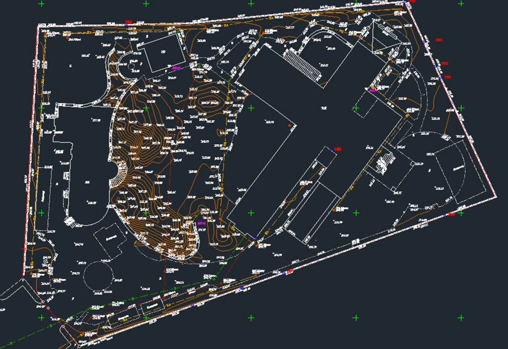
Image 16. Topographic plan of the site based on SLAM data
Accuracy, Data Density, and Error Accumulation
The thickness of the point cloud generated in real time is typically in the range of 2–3 cm and is reduced to approximately 1.5–2 cm on hard surfaces after post-processing. When a stable RTK solution is available, planimetric and vertical accuracy of around 5 cm can be achieved. In GNSS-denied environments, with georeferencing performed using ground control points, accuracy relative to control measurements can reach 15–20 mm.
Error accumulation during long, single-pass surveys without external correction is estimated at approximately 5 cm per 500 m. To minimise distortions, it is recommended to close scanning trajectories and to place control points at intervals not exceeding 200–250 m.
SLAM systems also have inherent sensor limitations: they do not provide the millimetre-level accuracy characteristic of static terrestrial laser scanners. Their practical accuracy limit is on the order of several millimetres for nearby objects, which is sufficient for topographic and cadastral surveying but inadequate for high-precision engineering monitoring. Consequently, SLAM should be regarded as an efficient complementary technology rather than a replacement for classical surveying methods in applications with strict accuracy requirements.
Video 2. 3D point-cloud model generated from SLAM scanning results
Performance and Hardware Requirements
Mobile laser scanning generates substantial data volumes: even surveys covering several hundred hectares can produce 300–400 GB of raw data. For stable and efficient processing, the following hardware specifications are recommended:
- at least 64 GB of RAM;
- high-speed NVMe SSDs for data storage and processing;
- a high-performance multi-core CPU and modern consumer-grade (gaming-class) GPUs;
- external drives or network-attached storage (NAS) systems for long-term archiving.
For large-scale projects, it is advisable to divide the dataset into separate sections, which reduces system load and helps prevent processing bottlenecks or software instability.
Practical Recommendations and Conclusions
Based on practical experience with SLAM technology in surveying, several key recommendations can be highlighted:
- Close scanning trajectories — loop closures significantly improve the stability and accuracy of the final result.
- Use an adequate number of ground control points (GCPs): a minimum of three per site; for larger areas, GCPs should be placed at intervals of 150–250 m.
- Monitor coverage in the field using the real-time point cloud, and take lighting conditions into account in advance when a colourised point cloud is required. For night-time surveys with RGB data, external lighting is necessary.
- Select processing algorithms flexibly: switching between High Precision and Fast modes often helps eliminate artefacts and improves model robustness.
- Plan storage and processing resources in advance — SLAM surveys generate large data volumes and require high-performance hardware.
Overall, SLAM scanners do not fully replace total station measurements and RTK surveying, but they complement these methods effectively. The technology is particularly well suited to large or complex sites and enables a single operator to capture substantial volumes of data even under challenging conditions, delivering high productivity with accuracy sufficient for the majority of engineering and topographic surveying tasks. With proper georeferencing and careful office processing, the resulting point cloud can be confidently transformed into a metrically accurate topographic plan.


