

Table of Contents
Introduction
Modern laser scanning technology revolutionises open-pit mine monitoring by enabling rapid, highly accurate surveying, production control, and slope stability analysis. Among the most efficient solutions for these tasks are the SLAM 100, SLAM 200, and SLAM 2000 mobile scanners. Their key advantages include mobility, exceptional measurement accuracy, and operational flexibility—functioning seamlessly with or without GNSS signals (even in jamming conditions).
 Figure 1. SLAM 100 scanner
This article details a high-precision survey of a large quarry (>100 hectares, >30 m elevation change), focusing on mobile laser scanning methodology using the SLAM 100 backpack system equipped with an RTK module for real-time high-accuracy generation.
We deliver:
- Fieldwork methodology;
- Characteristics of the digital output;
- Comparative analysis of SLAM technology vs. traditional surveying.
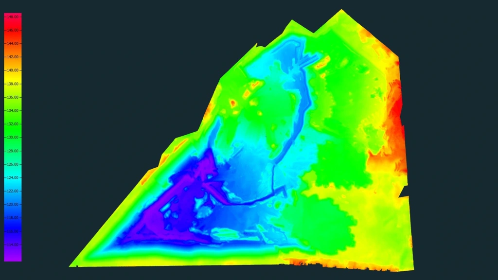 Figure 2. General quarry view
Why the SLAM 100 was selected for quarry scanning?
Previously, quarry monitoring was successfully carried out using aerial photography, which provided high efficiency with minimal labour costs and prompt results. However, at the current stage, aerial survey has become technically impossible due to the complete absence of GNSS signal at altitudes of 10 metres and higher.
To solve this problem and optimise production processes, an innovative approach was chosen - mobile laser scanning using the SLAM 100 system. This method is ideally suited to the specifics of operating quarries, where:
- Surfaces change rapidly due to heavy machinery;
- Frequent data updates are critical;
- Positioning conditions are challenging.
SLAM 100 advantages:
- Operates without GNSS;
- Tolerates signal dropouts;
- Efficient in GNSS-denied areas;
- A multiple increase in surveying speed compared to traditional methods.
Thanks to the application of this technology, the whole scope of field works was completed in record time - in less than 2 working days, which significantly exceeds the capabilities of classical geodetic methods.
How the quarry survey was conducted?
Preparation step
Prior to the start of field works, a set of preliminary measures was carried out to ensure maximum efficiency of the surveying process:
- Equipment setup:
- Fully charged SLAM 100 battery packs.
- Mobile device (smartphone) with an installed SLAM GO software for real-time scanning process monitoring.
- Route planning:
- Development of optimal operator movement trajectories
- Visualisation of complete coverage areas including:
- Working benches
- Slope edges
- Pit footings
- Minimisation of potential scanning blind spots
- Creation of a geodetic reference network:
- Marking and plan-altitude referencing of landmarks to control the accuracy of the final data.
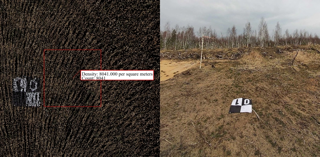 Figure 3. GCP visualization: RGB point cloud with density metrics.
 Figure 4. Field reconnaissance.
Scanning step
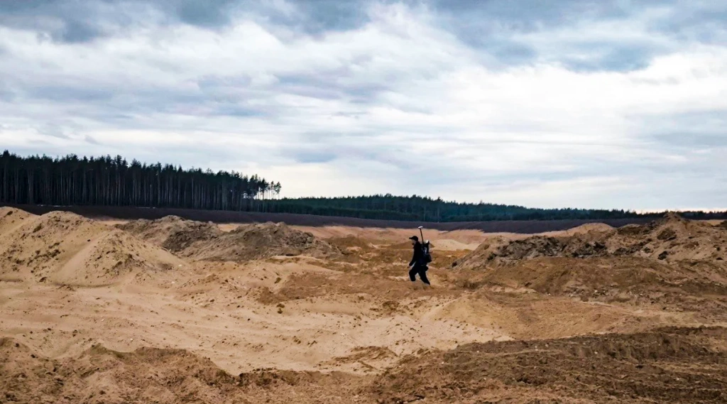 Figure 5. Backpack-mounted SLAM 100 system with RTK module.
As noted earlier, scanning was performed using an RTK module based on the UNICORE UM-982 chip. This innovative solution enabled complete elimination of ground control points (GCPs), direct point cloud generation in the local coordinate system, and high-precision positioning via corrections from the CORS reference station.
Pre-survey accuracy validation was conducted on two client-installed permanent benchmarks. The 13 km baseline to the CORS reference station maintained RTK corrections without data degradation.
After achieving fixed RTK positioning, the entire 100-hectare quarry was divided into logical survey sectors. An operator then performed sequential scanning using a backpack-mounted SLAM 100 system with RTK module, completing approximately 28 km of traverse lines.
GNSS signal stability was maintained throughout the traverse except for a single 250 meter long. To control the quality of the obtained data in this area, we additionally increased the % of data overlap, so that we could ensure their suitability. Concurrently, real-time data visualization via the SLAM GO app enabled rapid coverage monitoring and immediate gap correction during scanning operations.
Day two encountered severe weather: intermittent drizzle transitioning to intense rainfall. Operational pauses preserved data quality, with all survey objectives met within planned timelines.
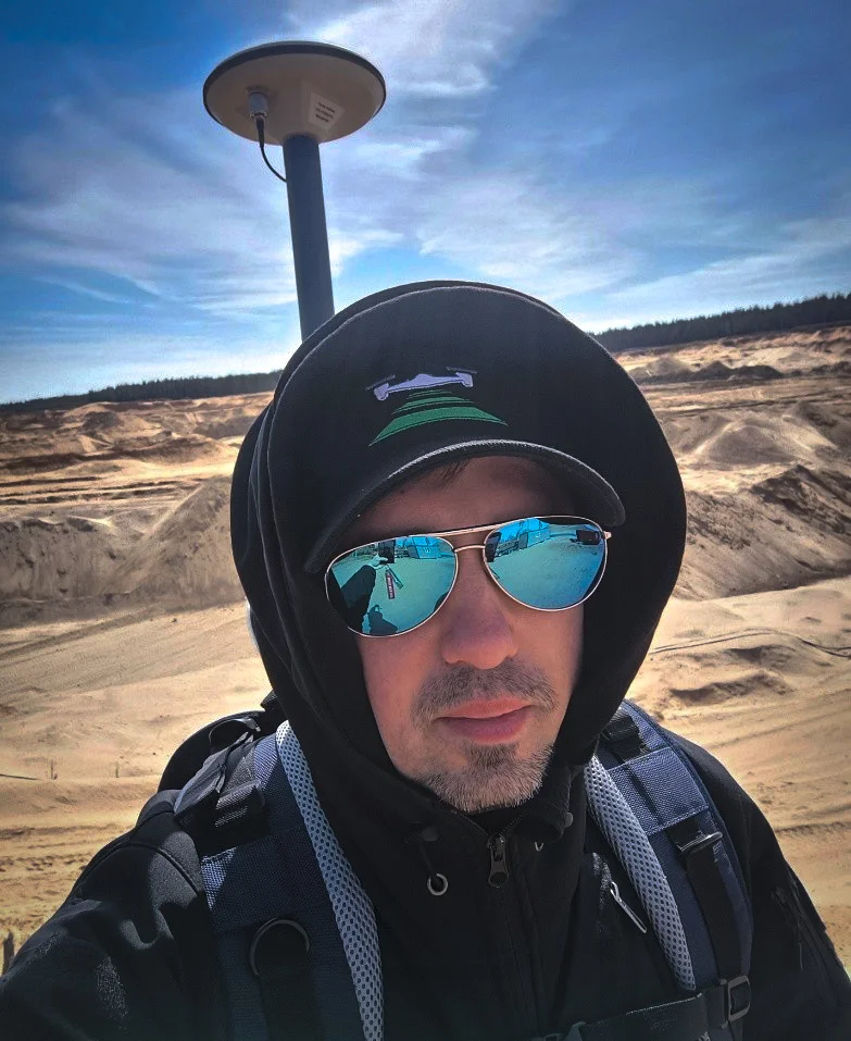
Figure 6. Backpack-mounted SLAM 100 with RTK module
Video 1. Scanning stage
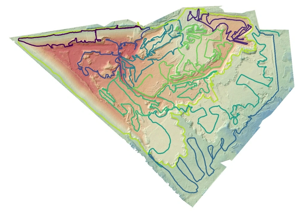
Figure 7. Overview map with all traverse paths
Data post-processing step
1. Point cloud generation and processing. The primary data processing included:- Automated generation of a dense point cloud using the standard SLAM GO Post software;
- Optimization of point cloud spatial distribution;
- Precise georeferencing in the target coordinate system using RTK trajectory data.
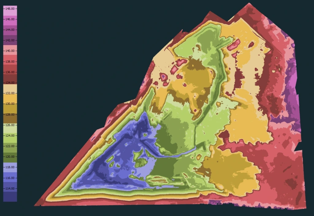
Figure 8. Point cloud colorized by elevation.
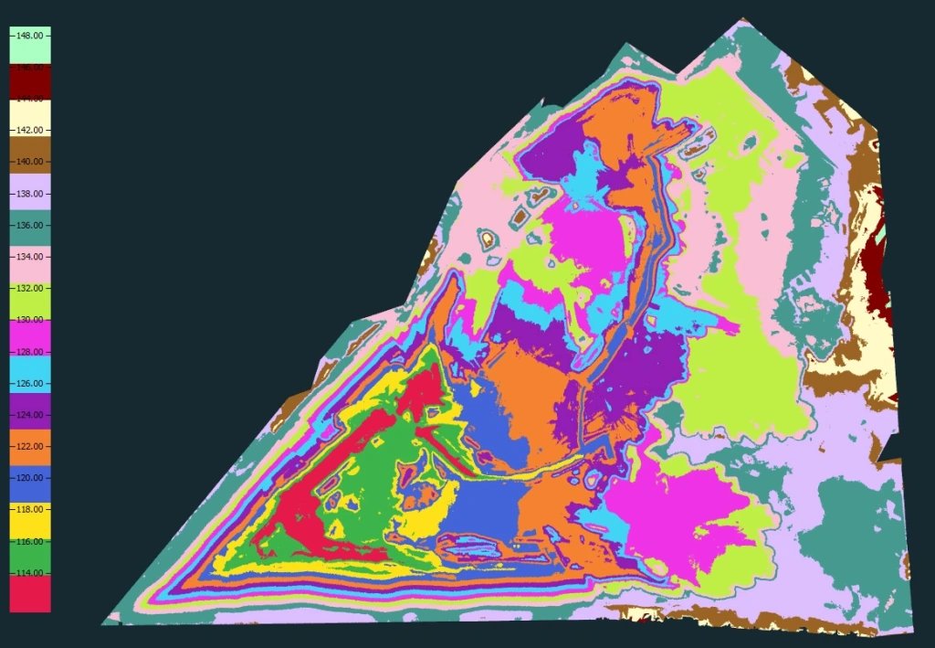
Figure 9. Point cloud colorized by elevation.
2. Data cleaning and classification. Comprehensive filtering was performed:- Dynamic objects removed (construction vehicles);
- Vegetation and scan artifacts filtered out;
- Ground points accurately classified.
- High-precision Digital Elevation Model (DEM);
- Contour lines:
- Base: 0.5 m spacing
- Index: 2.5 m intervals
- Deployment of a picket network with a density corresponding to a scale of 1:500.
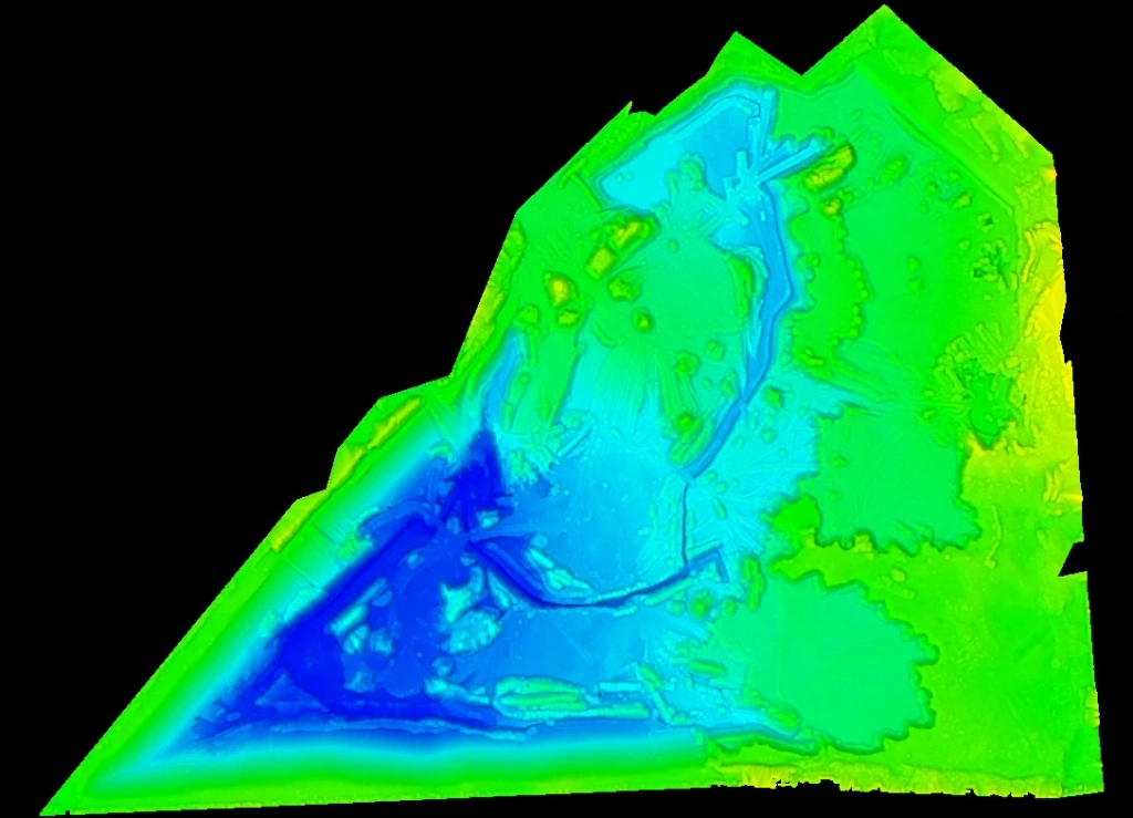
Figure 10. Digital elevation model.
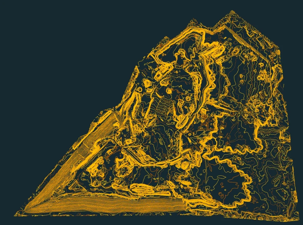
Figure 11. Contour lines.
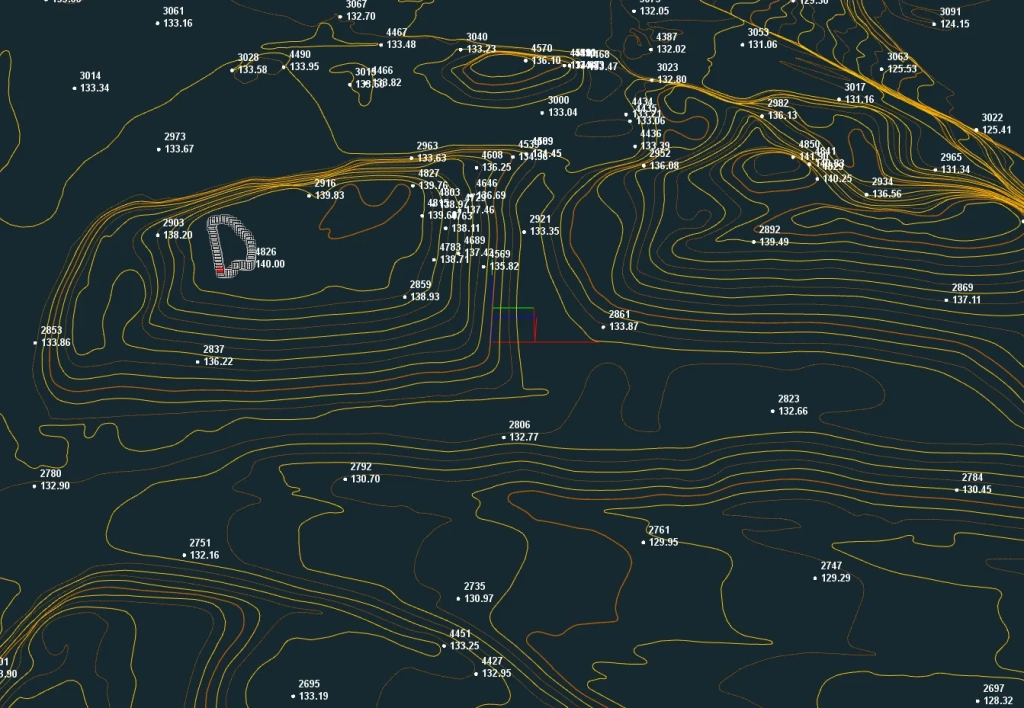
Figure 12. Contour lines and survey pickets
4. Quality control and analysis. A multi-stage accuracy verification was performed:- Visual data verification;
- Topological surface continuity analysis;
- Cross-validation against control points.
| № | X | Y | Z | H | dz |
| GCP-1 | 2263861.146 | 291800.019 | 134.211 | 134.2333 | 0.0223 |
| GCP-2 | 2263877.373 | 291487.738 | 139.176 | 139.2267 | 0.0507 |
| GCP-3 | 2263619.989 | 291219.029 | 142.290 | 142.3233 | 0.0333 |
| GCP-4 | 2263384.567 | 291959.923 | 132.575 | 132.6167 | 0.0417 |
| GCP-5 | 2263491.007 | 291884.847 | 123.809 | 123.84 | 0.031 |
| GCP-6 | 2263606.684 | 291780.832 | 123.205 | 123.22 | 0.015 |
| GCP-7 | 2263320.353 | 291827.357 | 133.391 | 133.4133 | 0.0223 |
| GCP-8 | 2263369.471 | 291569.831 | 120.513 | 120.55 | 0.037 |
| GCP-9 | 2263250.812 | 291511.787 | 123.85 | 123.9 | 0.05 |
| GCP-10 | 2262938.912 | 291588.296 | 118.246 | 118.2667 | 0.0207 |
Standard deviation: 0.022
RMSE (Root Mean Square Error): 0.034
Mean error: 0.032
Minimum error: 0.015
Maximum error: 0.0507
Table 1. Accuracy assessment
Upon completion, the customer received a final deliverables package containing:
- A high-density point cloud;
- Digital elevation models (DEMs);
- Contour lines and survey pickets.
To evaluate the performance of mobile scanning, the customer carried out a detailed comparison between the SLAM-derived data and the baseline surface previously generated using aerial survey data.
This comparative analysis made it possible to:
- Visualise the dynamics of terrain changes over the inter-survey period
- Quantitatively assess the accuracy of different remote sensing methods
- Evaluate the timeliness of results obtained using various technologies
- Identify the advantages and limitations of each method under specific operational conditions
Key advantages of the presented solution:
- Ability to integrate with previously acquired data
- Compatibility with various GIS platforms
- Data ready for direct use in design and planning
- Full metric and semantic accuracy of the information
This approach demonstrates the effectiveness of combining modern surveying technologies with traditional control methods, ensuring comprehensive monitoring of changes within the mining allotment.
Conclusion
SLAM 100 is an innovative solution for quarry surveying that saves time and enhances data accuracy. It is particularly useful in environments where stable GNSS is limited or entirely unavailable, yet rapid monitoring of terrain changes is required.
Where it is used:
- Mineral extraction monitoring
- Daily excavation control: Rapid scanning of benches and faces to record the current work status
- Volume calculations
- Slope monitoring
- Slope angle analysis: Creating accurate profiles to verify compliance with safety standards
- Planning and design
- Creation of up-to-date 3D models: Digital models of the quarry for mine planning
- Optimisation of machinery routes: Terrain analysis to determine the most efficient travel paths
- Stripping operations planning
If you need cost-effective quarry surveying, SLAM 100 is your best choice!
Need a demonstration or consultation? Contact TOPODRONE's SLAM technology specialists.